
—————————————————————————————–
V2-19Sept2020
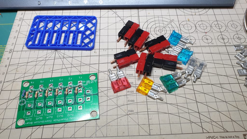
1. After soldering the resistors and fuse leds onto the main board, insert the powerpole contacts (with their copper wire extensions) into the red and black housings, and place fuses in the spade sockets (as per main instructions).
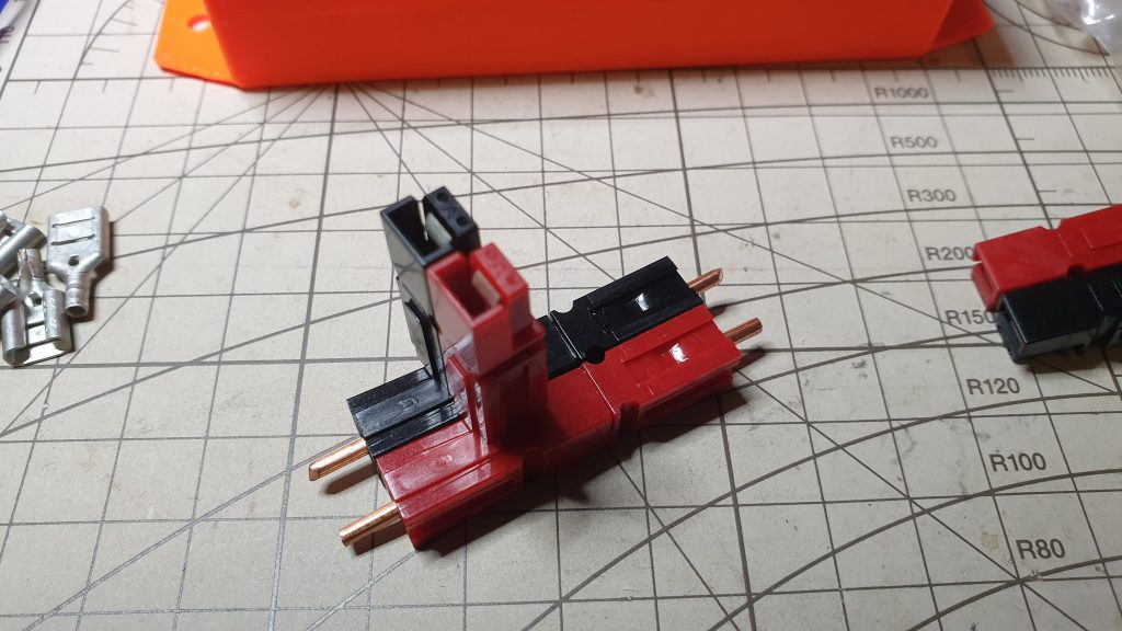
2. Check that the powerpole connector contacts are properly inserted, by inspection and joining together, should make good connection and positive click.
3. Place Fuses in spade sockets into the board, and Powerpole connectors in their positions as shown.
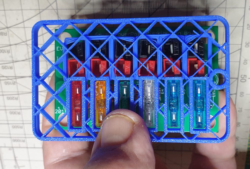
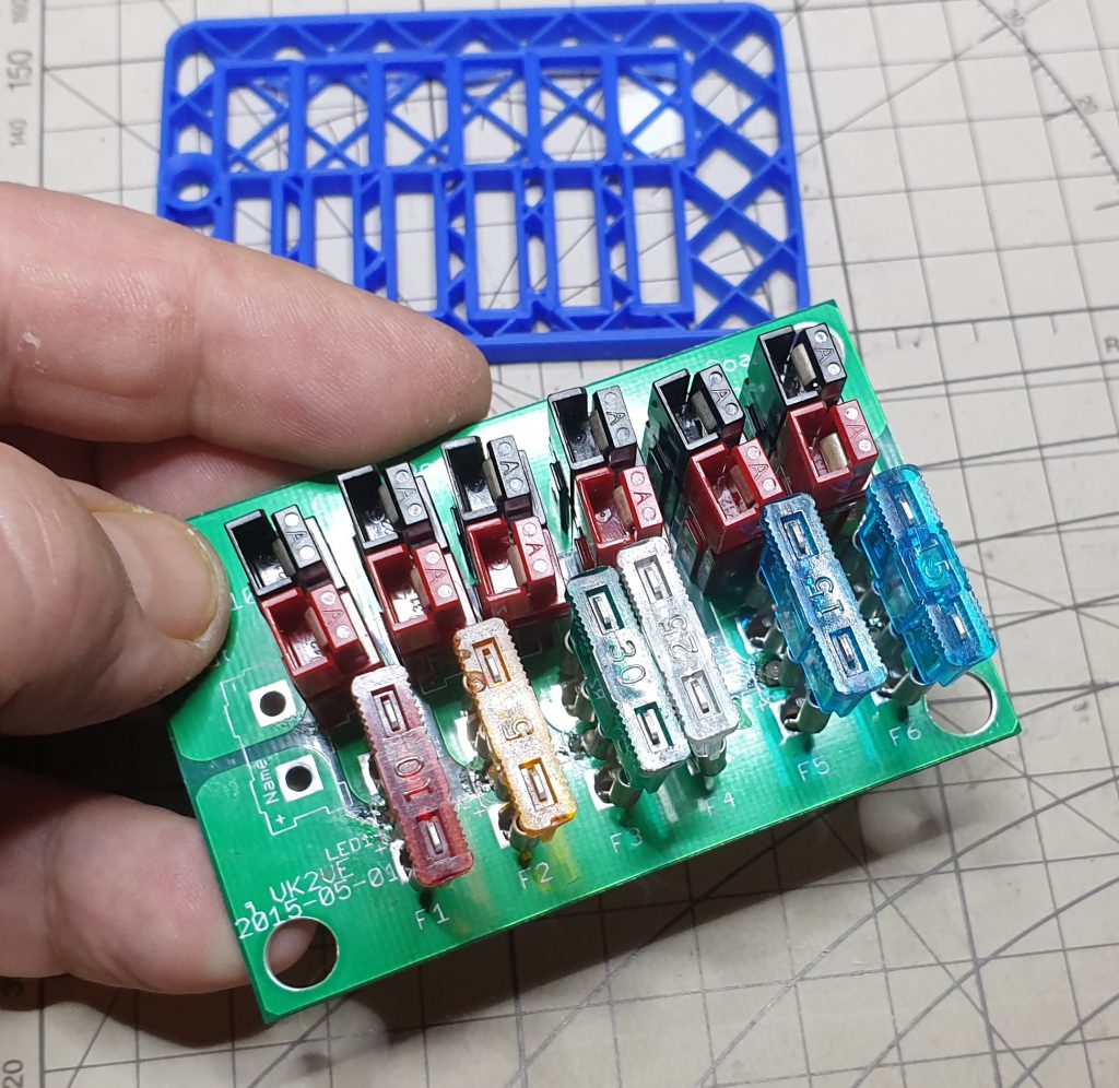
4. Position jig over parts so that they are aligned properly (several minutes of fiddling)!
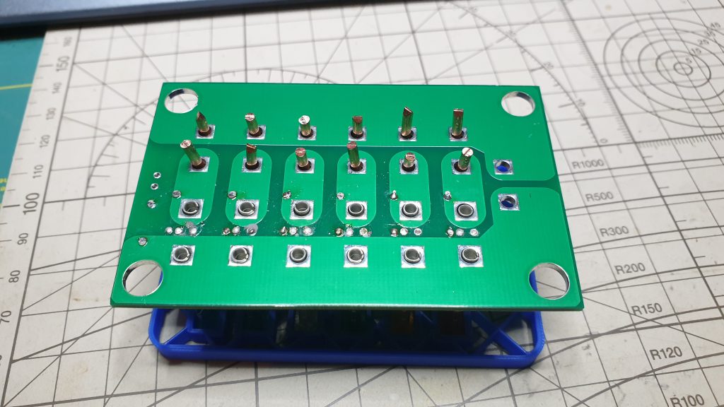
5. Flip over and push fuse connectors down. They should be almost flush with the main board.
Tack solder the Fuse socket contacts to the board (but not the Powerpole connectors).
Next, solder all the other fuse connections and then come back to
solder the inner fuse connections. Do not solder in the power pole
connectors at this stage. Note that, with the jig, the initial tack
soldering only provides an electrical connection to the fuse holder but does not provide enough mechanical support for the fuse holder. You need to solder the sides of the legs and the top to achieve a durable mechanical connection.
With the jig holding fuse and power pole components in place, tack solder each fuse contact closest to the centre of the middle of the main board, i.e. those on the small copper islands, as they will soak away far less heat.
Flip board over to drop off all the Powerpole connectors (because it will be much easier for access) and properly solder both sides of fuse sockets onto the board. Then reassemble the jig with Powerpole connectors and continue the main instructions.