Photo's for the THE RESTORATION OF VALVED HIGH FREQUENCY COMMUNICATIONS RECEIVERS ebook.
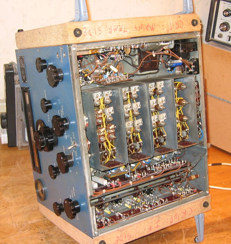
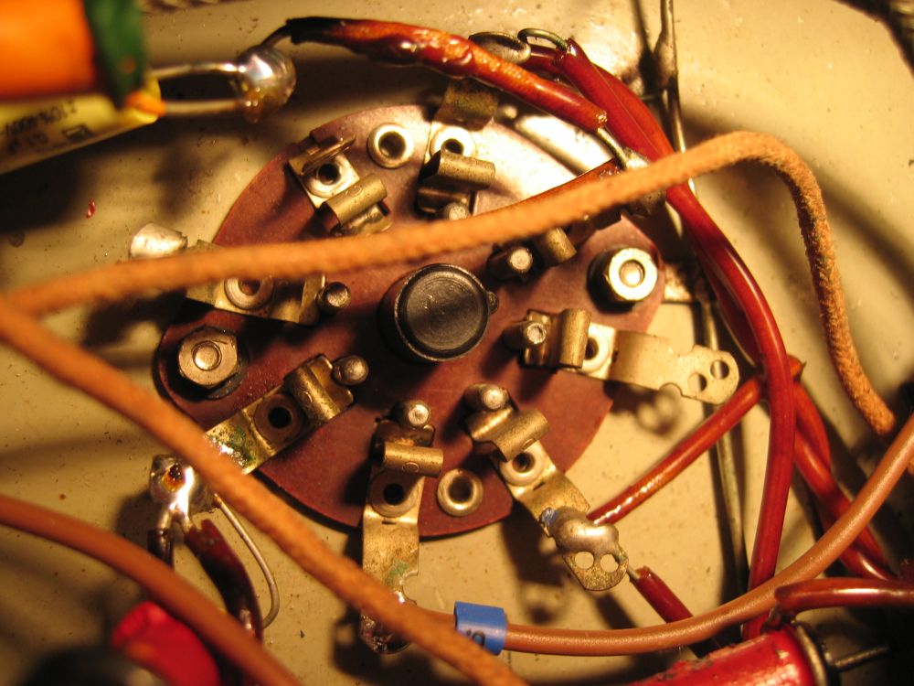
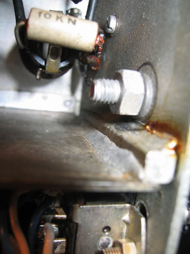






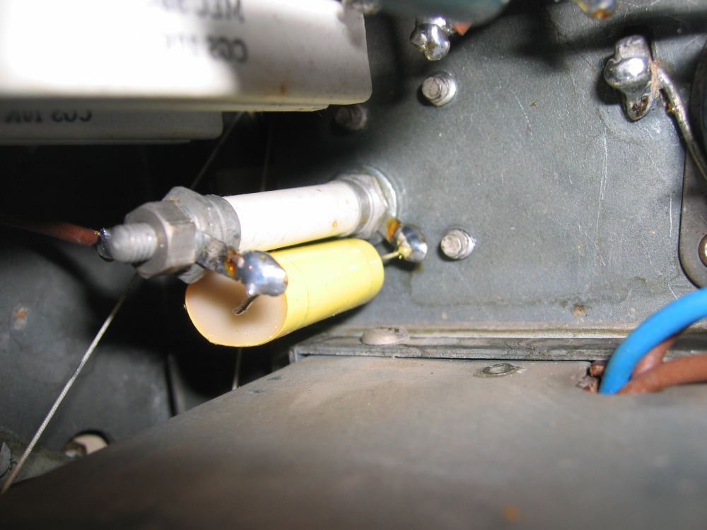

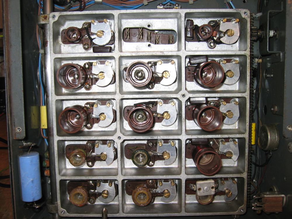

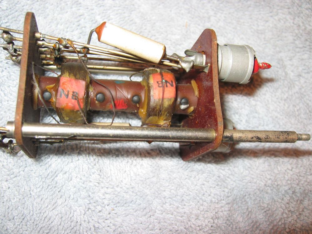
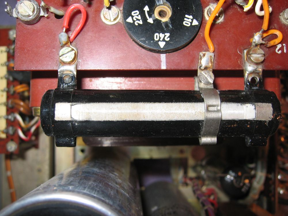
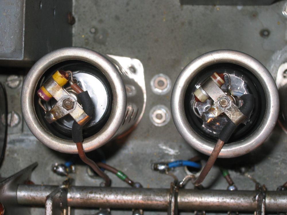
GEC BRT400 Mk1 IFT carries 240VDC between the RHS (secondary) bobbin and its overwinding, shown here. There is no gap and no meaningful insulation so flashovers are common, especially in damp conditions. Notice the Philips beehive trimmer, a type prone to short circuits. Later BRT400D IFTs had mica fixed capacitors but kept the beehives.
| Album | 2-Parry |
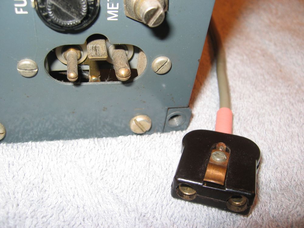

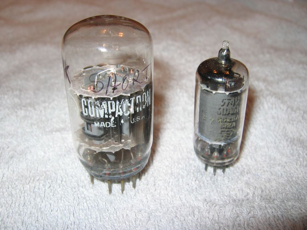

Acorn glass triode which seats into this type of special ceramic socket for the Hallicrafters S36 receiver. Also shown is a later, more advanced 6CW4 nuvistor triode which was in volume production for USA TVs for a couple of years.
These were very high technology devices employing ceramic/metal seals.
| Album | 2-Parry |

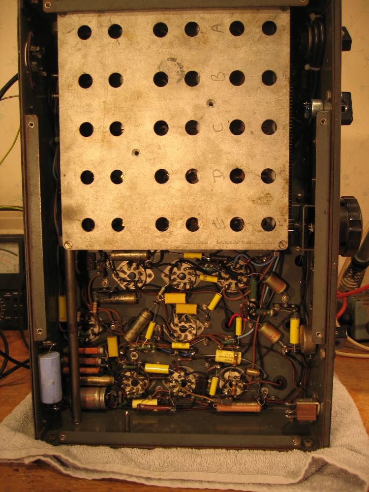

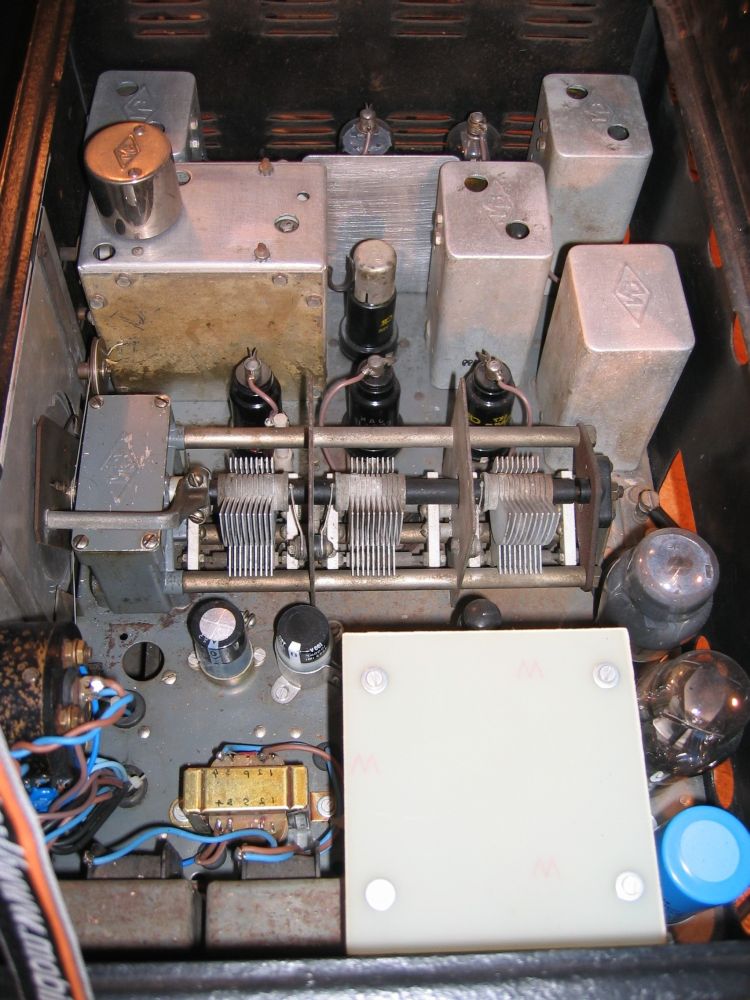
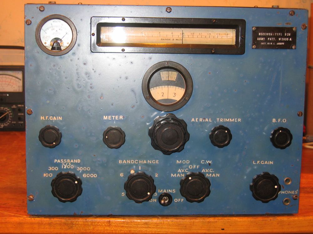
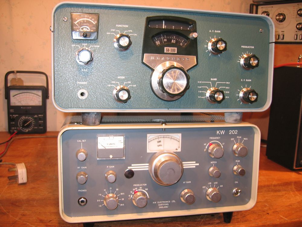
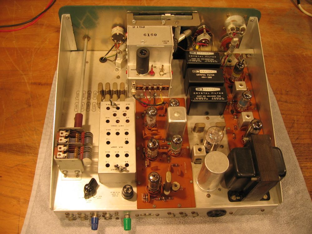
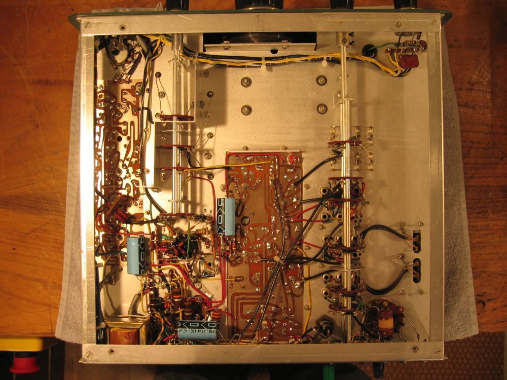
KW202 topside, showing lots of wires. The vertical PCB in the foreground is the calibrator, and at rear left is the solid state notch & Q-multiplier board. Notice the writer’s black plastic cover over the VFO capacitor, to reduce drift. Also notice the yellow Kapton tape covering a hole on top of the VFO box. This is directly below the lid finger hole. It stops unwanted rubbish getting into the VFO.
| Album | 2-Parry |
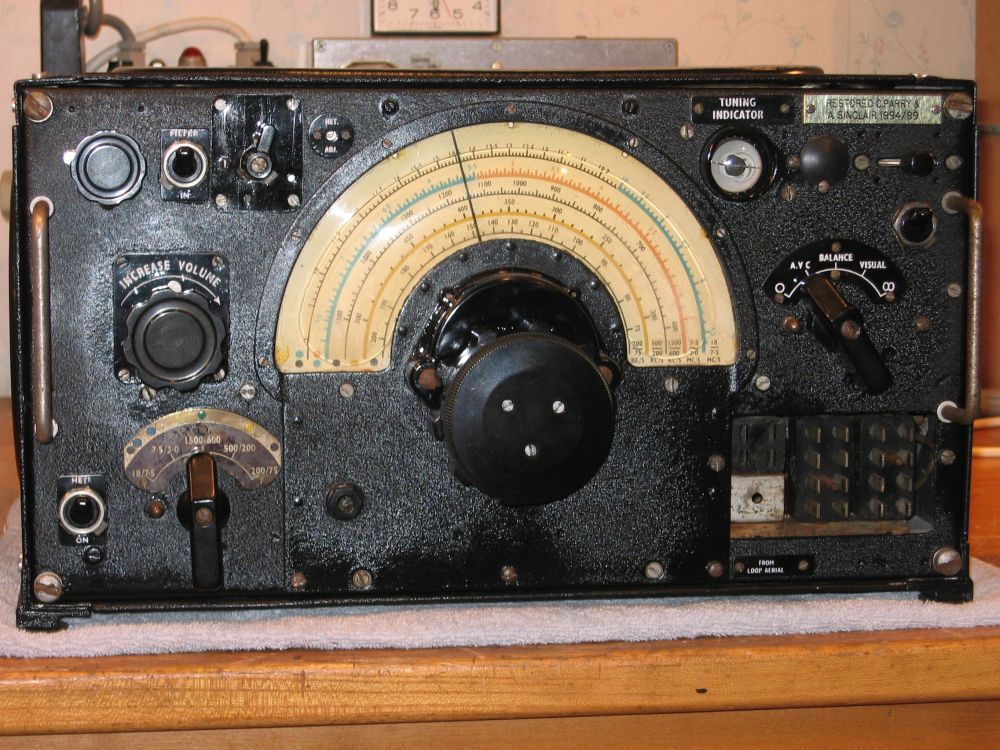
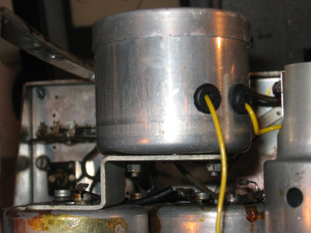
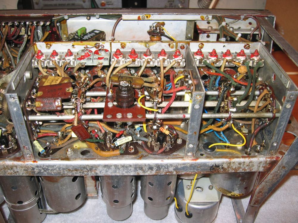
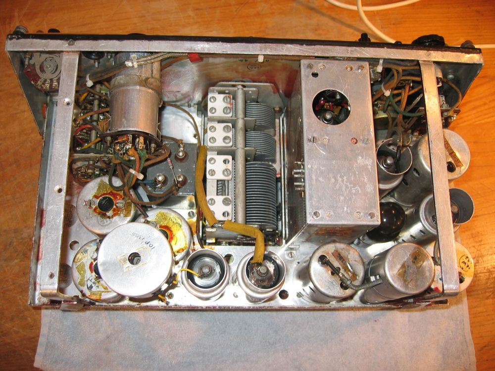
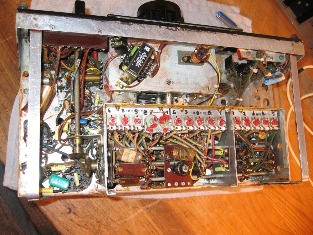
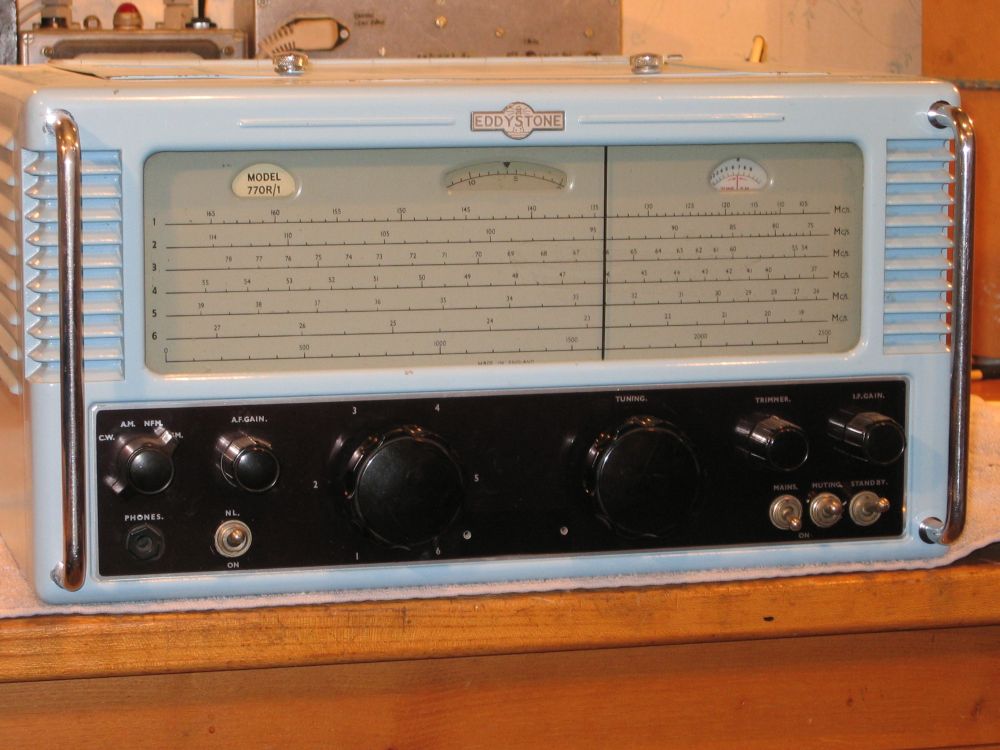
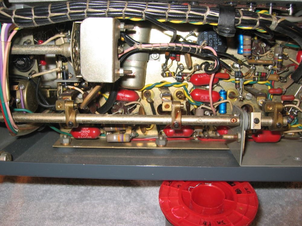
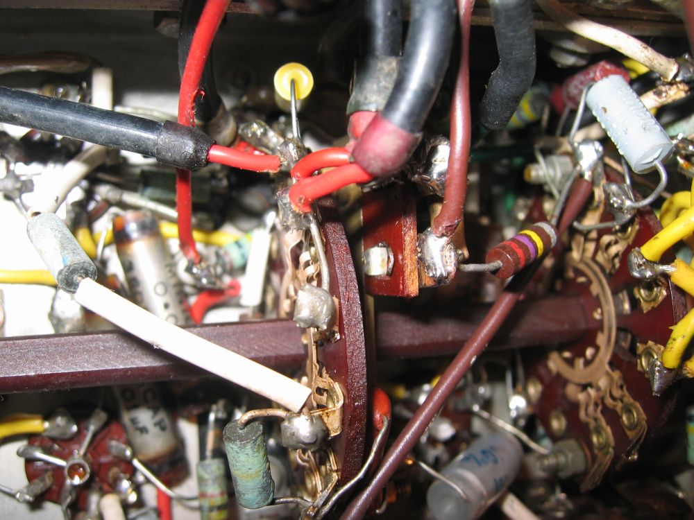
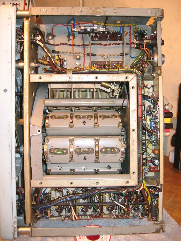
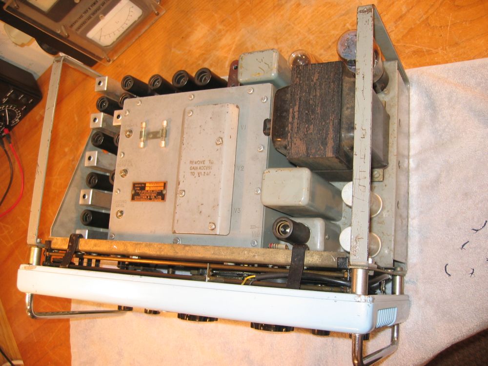


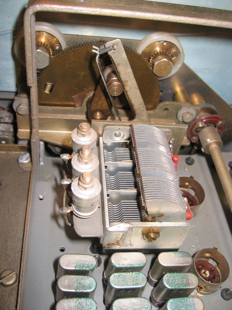
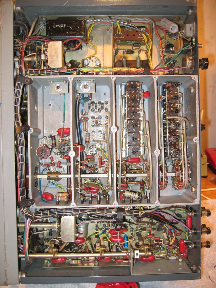

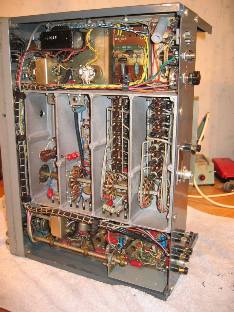
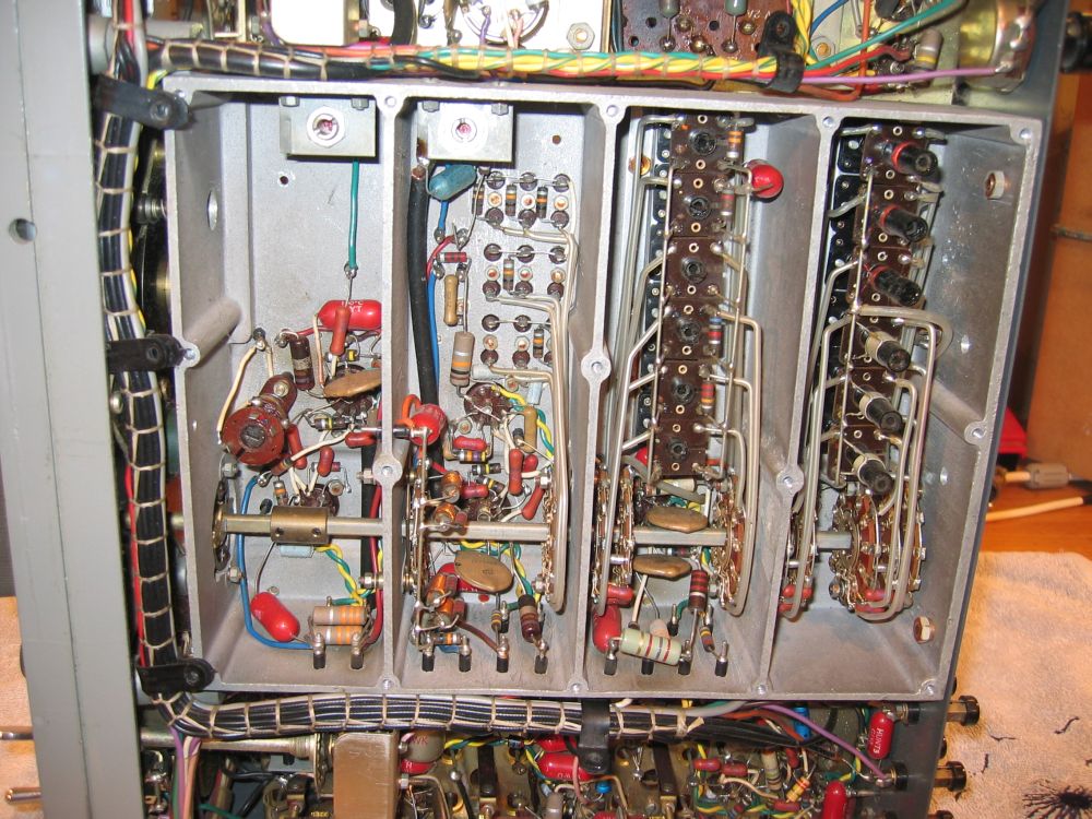

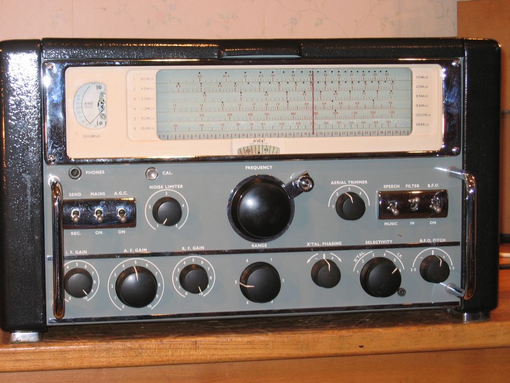

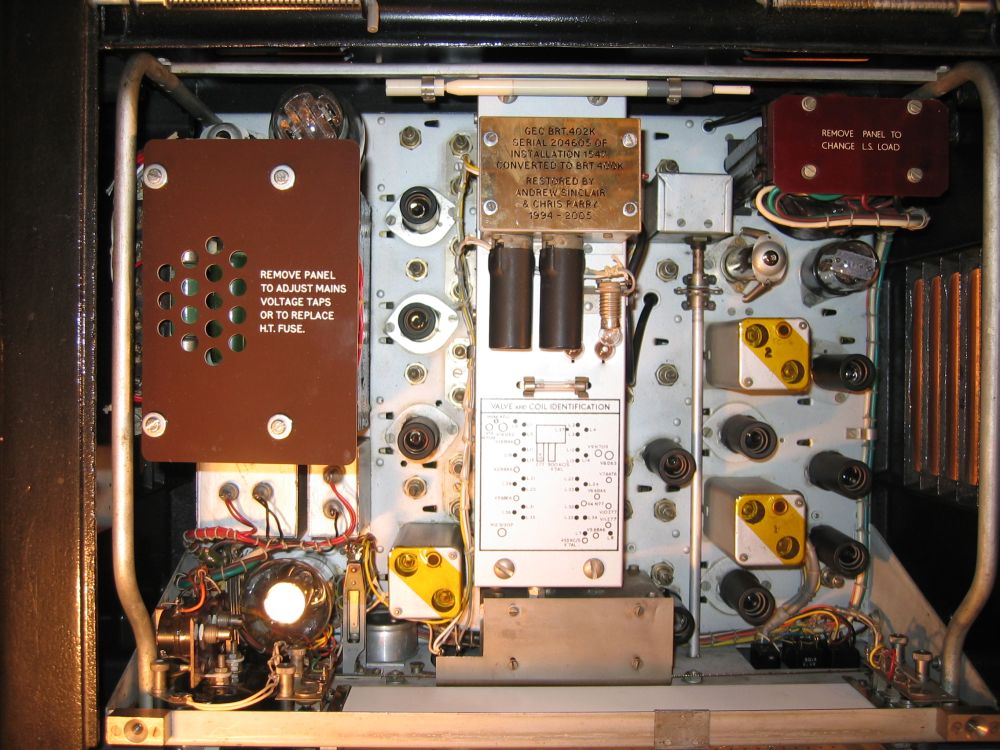
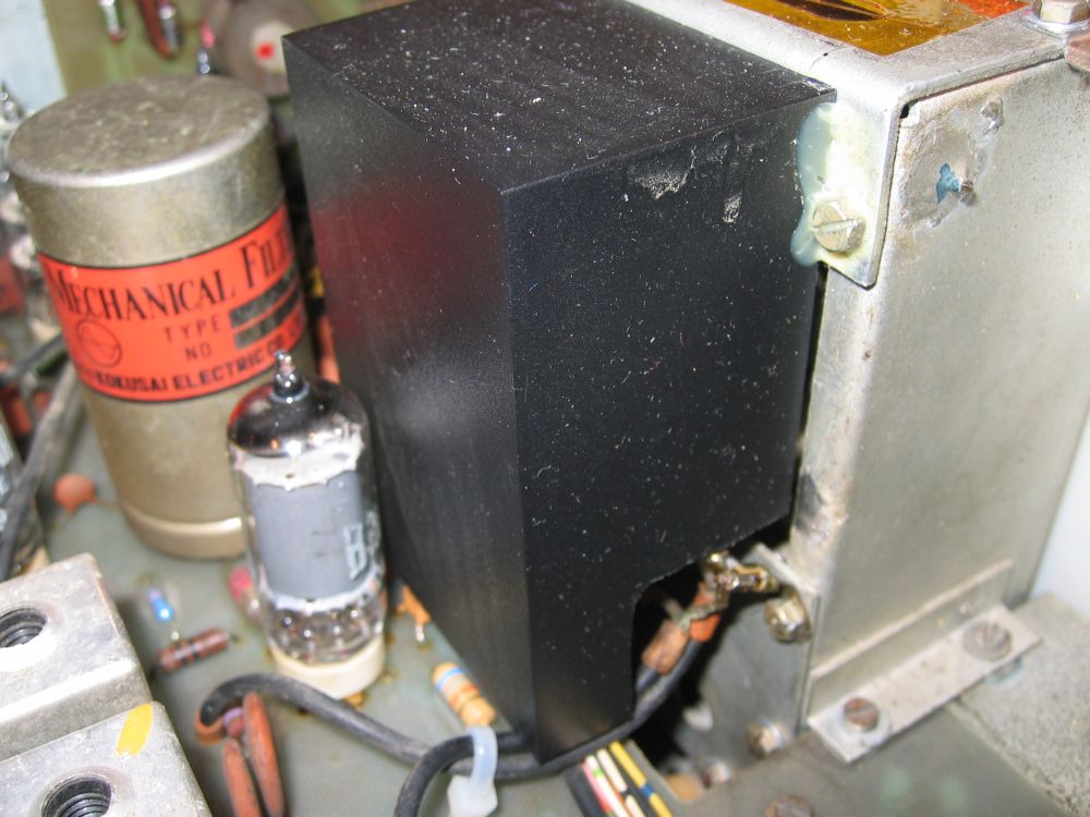
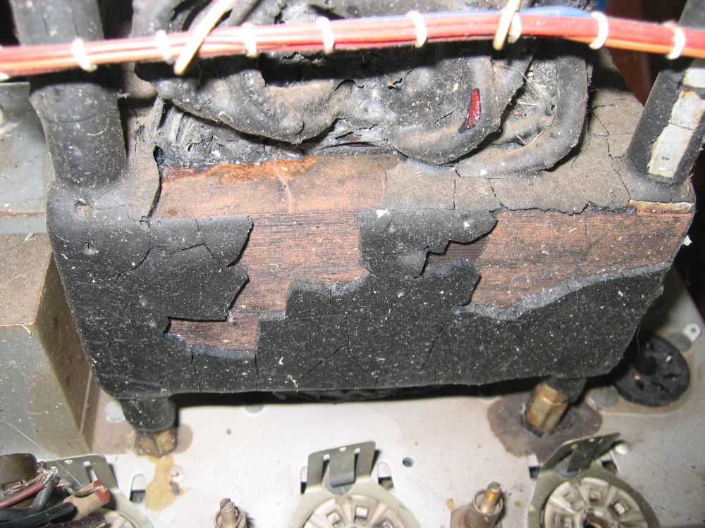
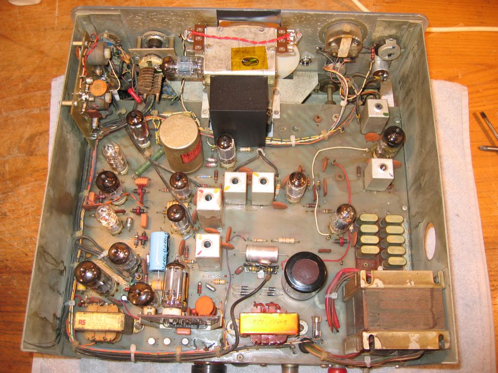
GEC BRT400K chassis topside view showing a new mains transformer cover. This set started as a BRT402K, and was later given the correct table cabinet to convert it into a BRT400K. Note Kapton tape over the IFT holes, to keep dirt out. Beehive trimmers make this a very sensible precaution. Notice the adaptor plates used to fit B7G valves into chassis holes originally used for B8G types.
| Album | 2-Parry |

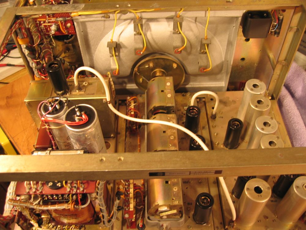
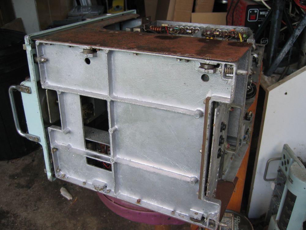
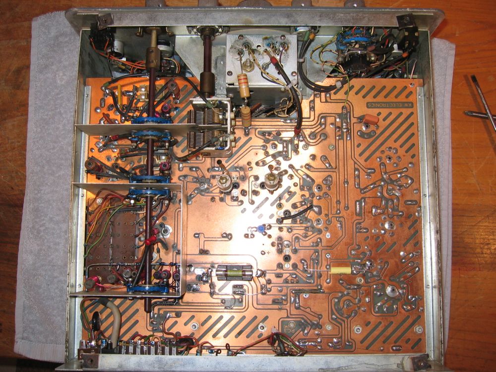
GEC BRT400K chassis underside view showing the set as easier to work on than is actually the case. Notice the heavy metal cover over the LO compartment, and also notice the BFO cover at the top right. Equally notice the lack of any proper covers over the aerial, RF amplifier and mixer sections of the bandchange compartment.
| Album | 2-Parry |